
CBD08, short for “” Can Bus Distribution “” with 8 connections – why do you need this module?
Connecting Can Bus devices in your vehicle can sometimes be a real challenge. It requires a clean laying and connection of Can Bus cables, the provision of electricity for the devices and the search for a suitable way to schedule the Can Bus. In addition, there is often a need for several Can buses to meet various requirements – such as the drive Can Bus, the comfort Can Bus and a programming Can Bus (USB2CAN), to name just a few.
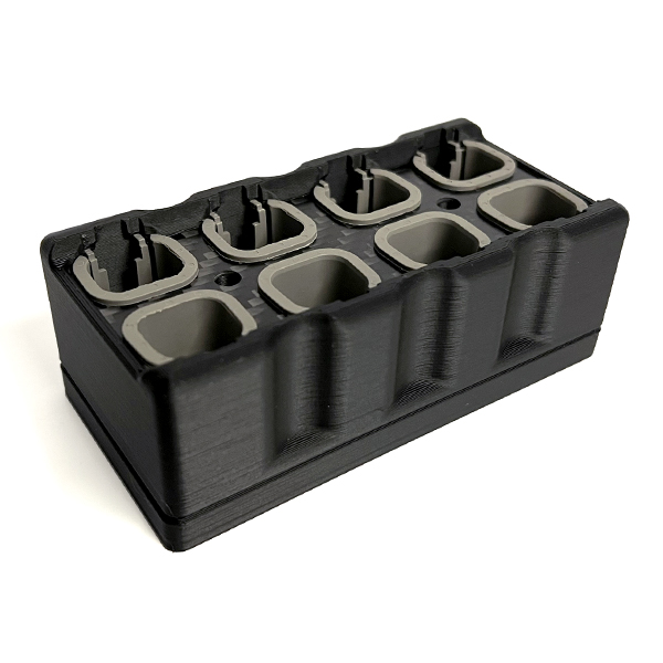
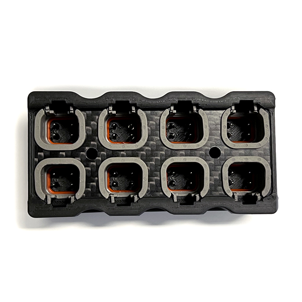
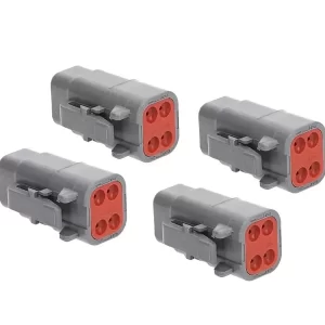
To address this problem, CANchecked has developed a practical additional module with 8 connections. Each connection has four wires: Can High, Can Low, 12V and ground.
The CBD08 hardware – With dimensions of only 96x47x33mm, the box is incredibly compact and fits practically anywhere. The connections are designed according to the widely used DTM04-4P design. Matching sockets, DTM06-4S, can optionally be purchased to complete the installation. Two holes are provided in the middle for fastening and you can use the two screws supplied.
Under the lower lid there are jumpers on the circuit board:
On the left, JP3 and JP4 connect both Can buses (Can Bus 1 and Can Bus 2). When both jumpers are removed, both Can buses are separate, each with four connections.
JP1 activates the Can Bus termination for Can Bus 1.
JP2 activates the Can Bus termination for Can Bus 2.
The box can optionally be equipped with a 12V / mass supply line. This can then be tapped by the other connections to supply the end devices with electricity. However, devices with higher power consumption should not be supplied with power via the module. In such cases, you should only connect them via the Can Bus lines and set up a separate power supply.
If you choose the standard configuration, all 8 Can Bus connections are connected, and both Can Bus termination resistors are activated.
 CBD08 - CAN Bus Distribution
| 5 star | 100% | |
| 4 star | 0% | |
| 3 star | 0% | |
| 2 star | 0% | |
| 1 star | 0% |


© 2024 G-4C Store | All Rights Reserved | Developed by


Customer service and delivery was quick and perfect!